Nov 19, 2020
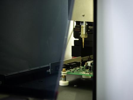
Practice has confirmed that the most time-consuming stage of board repair is the process of troubleshooting. This problem is especially relevant for repair shops and electronics companies, where the flow of testable printed circuit boards is huge.
Manual testing can take a significant part of the specialist's time, who will simply "ring out" all the pins of microcircuits on the boards. The solution to the problem can be automated testing using signature analysis systems. However, even here you can face the problem of lack of documentation for the board. This problem is not relevant if there is documentation or if we are talking about new boards, the documentation for which is publicly available.
What if the boards have been produced for a long time, and the documentation has been lost? In this case, intelligent recognition systems can help, which will allow you to identify component pins without documentation for the board.
Let's look at how the troubleshooting was carried out using such a system on the STM32F429 board.

When connected to a PC, the board should be identified as ST-Link, but this did’t happen, the board was recognized as an Unknown device. Also, when connected, the U1 microcircuit was heated. Based on this, it was assumed that the problem lies in the part of the ST-Link programmer, so it was tested first of all. Testing was carried out using the EyePoint P10 automated signature analysis system.
Such a system uses smart scanning technology to locate components. When the pins of the microcircuits are found, the testing process starts. With the help of a flying probe, the I - V characteristics are taken from each output in turn. This is how the reference and faulty boards are scanned. Then the I - V characteristics of the corresponding conclusions are compared and the serviceable and faulty outputs are determined. The test signal parameters, as well as the signature comparison threshold, are set by the tester independently.
In this case, testing was done with test signal settings of 12V, 2.5mA and 100Hz. Only that part of the board that belonged to ST-Link was scanned. There were differences in the signatures of the conclusions, which are indicated by red dots in the photograph. Signature differences were 35% or more.

The conclusions with the signature mismatch of the U1 microcircuit were examined in detail. This microcircuit was heating up, in connection with which there was a suspicion that it was out of order. The pinout of the microcircuit in the SOT-23-5 package is shown in the diagram.

The following I - V characteristics were observed at pins 1 and 3.


According to the form of this I - V characteristic, we can say that the tested board has a short to ground through a small resistance, probably this is the resistance of the burned out microcircuit itself, and on the standard we see the I - V characteristic of the pn junction + large capacitor chain.
At pin 4, the following I – V characteristics were observed.

The resulting I - V characteristic indicates that there is an additional problem in the pn junction + capacitor circuit - there is no capacitance, which indicates a capacitor breakdown.

The points highlighted in yellow are connected to pin 3 of the U1 microcircuit as they have the same IVC.

The difference between the I - V characteristic of the tested board and the reference one at the points marked in blue and red is most likely due to a problem in the U1 microcircuit. Therefore, we will try to determine what kind of microcircuit it is. To do this, you need to use the diagram or the list of components for the board.
According to the BOM on the board, U1 is an LD3985M33R chip, a 3.3V voltage converter with a maximum input voltage of 6V. Probably, a voltage higher than 6V was accidentally applied to the board, which led to the failure of the microcircuit.
According to the datasheet for the LD3985M33R chip, pin 1 is the input, pin 3 is the Enable signal to control the chip, and pin 4 is needed to minimize the noise of the internal reference voltage.
We measured the output voltages on the reference board and on the faulty one on pins 1, 4 and the Enable signal on pin 3.
On the faulty board, there was a voltage drop at pins 1 and 3 at 0.4 V, this indicates that the microcircuit was partially burned out. Considering that the microcircuit produces the correct output voltage but at the same time it has a low internal resistance, the output current of the microcircuit is very small and it is not enough for the operation of the ST-Link programmer microcircuit.
After removing the microcircuit from the board, the voltage at the input contact immediately increased to 4.9V, that is, to the USB supply voltage, which means that the cause of the voltage drop was eliminated.
After replacing the microcircuit, the I - V characteristics at the input 1 and output 5 of the microcircuit were checked, but with the help of the EyePoint u21 or EyePoint u22 desktop devices and the epLab program. The resulting I – V characteristics are presented below.
 I - V characteristic at pin 1
 VAC at pin 5
Checking the pins highlighted in red and yellow showed that the I - V characteristics at these points are the same. However, the I - V characteristics of the pins highlighted in blue are still different.
When connecting the board to a PC, it was found that sometimes it is detected as ST-Link, but there are still problems - the “USB Communication Error” error appears. In this regard, it was decided to retest the blue dots as they are associated with USB operation.
The following I - V characteristics were obtained: