Dec 03, 2021
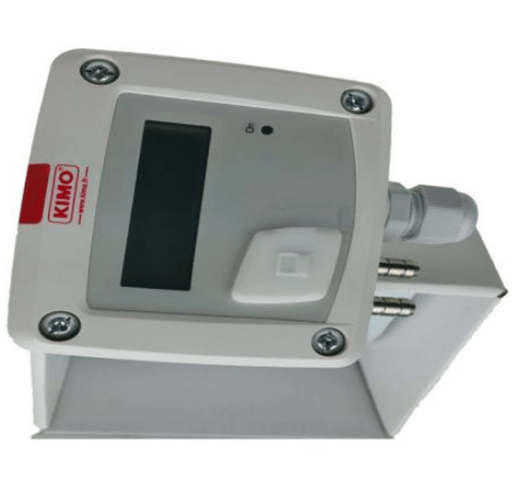
Differential pressure transmitter is a kind of pressure measuring instrument widely used in all kinds of chemical industry.
Working principle of differential pressure transmitter is as follows.
The differential pressure from the two-sided pressure pipes acts directly on the two-sided isolation diaphragm of the differential pressure transmitter sensor, and is transmitted to the measuring element through the sealing fluid in the diaphragm.
The measuring element converts the measured differential pressure signal into the corresponding electrical signal and transmits it to the converter. After amplification and other processing, it becomes the standard electrical signal and then is output.
1. Measurement Objectives of Differential Pressure Transmitter
Differential pressure transmitter can not only measure the differential pressure value, but also measure the following three physical quantities through the analysis and calculation of the differential pressure value.
1.1 Pressure
You can just choose a section of pipe on the whole pipe to test its pressure, i.e. to detect the pressure of the pipe through differential pressure transmitter and secondary meter.
1.2 Flow
The differential pressure transmitter is installed through the pressure difference between the front and back of the flow orifice plate, which is matched with the square root secondary meter to measure the flow in the pipeline.
1.3 Resistance
If you want to measure the pressure difference between the inlet and outlet of the tower, you can install a pressure pipe at the inlet and outlet respectively, then connect the differential pressure transmitter, and finally match with the secondary meter to measure the tower resistance.
In general, with the development of social industrialization and the continuous improvement of petrochemical and steel automation level, the application scope of differential pressure transmitter is more and more extensive.
However, there is also increasing number of problems in production.
For example, different installation, use and maintenance personnel make it more difficult to solve problems quickly, which affects the normal production to a certain extent, sometimes even endangers the production safety.
Therefore, the field instrument maintenance personnel must have advanced techniques and skills for the instruments.

Figure 1: Rosemount Differential pressure transmitter 3015CD4A22A1AB4M5
2. Scenes Suitable for Differential Pressure Transmitter
In order to prevent the medium in the pipeline from entering the transmitter directly, the pressure sensing diaphragm is connected with the transmitter by a capillary pipe filled with fluid.
The differential pressure transmitter is used to measure the liquid level, flow and pressure of liquid, gas or steam, and then convert the detected information into 4 ~ 20mA DC signal for output.
Differential pressure transmitter is suitable for the following measurement and control situations.
Viscous medium at high temperature.
Medium easy to crystallize.
Precipitation medium with solid particles or suspended substances.
When your medium is strong corrosive or highly toxic, using a differential transmitter can avoid pressure pipe leakage from polluting the surrounding environment. And it also helps to avoid the cumbersome work of often replenishing the isolation fluid due to the unstable measurement signal when using the isolation fluid.
When you continuously and accurately measure the interface and the density remote transmission device, you can avoid the mixing of different instantaneous media, so that the measurement results can truly reflect the actual situation of the process change.
In occasions that require high hygiene and cleanliness, such as food, beverage and pharmaceutical industry production, not only is it required that the part of the transmitter contacting the medium meets the hygienic standard, but also it is easy to wash to prevent cross contamination of different batches of medium.

Figure 2: KIMO Differential Pressure Transmitter CP101-PN
3. Troubleshooting Methods of Differential Pressure Transmitter
In the process of measurement, the differential pressure transmitter often has some problems or failures. For such occasions, the timely judgment, analysis and treatment of the breakdown is very important for the ongoing production.
According to the experience of daily maintenance, we summarized some problem analysis methods and solutions.
3.1 Investigation Method
Recall the abnormal phenomena before the failure. For example, lighting, smoking, peculiar smell, power supply change, lightning, humidity, misoperation and maintenance, etc.
3.2 Visual Method
You need to observe the external damage of the circuit, the leakage of the impulse pipe, the overheating of the circuit and the state of the power supply switch, etc.
3.3 Detection Method
* Open Circuit Detection
First of all, you need to separate the suspected part from other parts to see if the problem disappears. If it disappears, you can find the fault. If it doesn't disappear, go to the next step.
For example, when a smart differential pressure transmitter can't carry out normal Hart remote communication, you can disconnect the power supply and use the method of additional power supply on site to power on the transmitter for communication, so that to check whether the cable interferes with the communication due to the superposition of electromagnetic signal of about 2KHz.
* Short Circuit Detection
In the case of ensuring safety, you need to directly short the relevant part of the circuit.
For example, if the output value of differential pressure transmitter is too small, you need to disconnect the pressure pipe, direct the differential pressure signal from the primary pressure valve to both sides of the differential pressure transmitter, and then observe the output of the transmitter to judge the connectivity of the blockage and leakage of the pressure pipe.
* Replacement Detection
Replace the suspected part to determine the fault location.
For example, when you suspect that the transmitter circuit board is faulty, you can temporarily replace it to find the cause.
* Partial Detection
The measurement circuit is divided into several parts, such as: power supply, signal output, signal transmission, signal detection.
You can check in parts, narrow the scope of the check to find out the fault location.

Figure 3: Atlas Copco Differential Pressure Transmitter 1089057543
4. Typical Problems of Differential Pressure Transmitter
4.1 Pressure Pipe Blockage
We will take the blockage of positive impulse pipe as an example to analyze the fault phenomenon of impulse pipe blockage.
In instrument maintenance, due to untimely discharge of differential pressure transmitter's pressure pipe, or dirty and sticky medium, it is easy to cause blockage of positive and negative pressure pipes.
The performances of blockage are: transmitter output decreases, rises or remains unchanged.
* Pressure Pipe Blockage Analysis
When the flow rate increases, the influence on the output of the transmitter (square root of the output signal of the transmitter itself):
Assume that the original flow rate is F1, P1 = P1 + - P1 -, f'1 = K,
F'1 is the transmitter output value before the change.
Suppose that the increased flow rate is F2 (that is: F2 > F1), P2 = P2 + - P2 -, f'2 = K
F'2 is the output value of the transmitter after the flow is increased.
Because the positive pressure pipe is blocked, when the actual flow is F1 and F2 respectively, that is P1 + = P2 +;
When the flow rate increases, P2 - has the following changes: because the actual flow rate increases to F2.
Compared with the original flow rate of F1, the static pressure in the pipeline increases correspondingly.
Assume that the increase value is P0, and P2 - the static pressure caused by the increase of fluid velocity in the pipe decreases, and the decrease value is P0 '.
The relationship between P2 - and P1 - is: P2 - = P1 - + p0-p0 '.
Then: P2 = P2 + - P2 - = P1 + - (P1 - + p0-p0 ') = P1 + (P0' - P0)
Then: F '= k.
So: when p 0 = P 0 ',
Then: F'2 = k = k, f'2 = f'1 transmitter output remains unchanged.
When p 0 > P 0 ', f'2 = k = k, f'2 = K.
When p0f'1, the transmitter output becomes smaller.
When the flow rate decreases, the influence on the output of the transmitter (the transmitter itself conducts the square root of the output signal) is analyzed.
Assume that the original flow is F1, P1 = P1 + - P1 -, f'1 = k, and f'1 is the transmitter output value before the change.
Set the reduced flow rate as F2 (that is: F2 > F1), P2 = P2 + - P2 -, f'2 = k, and f'2 is the output value of the transmitter after the flow rate is reduced.
Because the positive pressure pipe is blocked, when the actual flow is F1 and F1 respectively, P1 + = P2 +;
When the actual flow rate is reduced from F1 to F2, the static pressure in the pipeline will also decrease correspondingly, and the decrease value is P0;
At the same time, when the actual flow rate drops to F2, the P2 value also increases because of the decrease of the flow velocity in the pipe. The value of rise is set to P0 '.
Here, the relationship between P2 and P1 is: P2 - = p1--p0 'P2 = P2 + - P2 - = P1 + - (p1--p0 + P0') =p1+ (p0-p0 ')) f'2 = k = k
This way: when P0 = p0', the output of f'2 = k = k f'2 = f'2 transmitter is unchanged.
When P0 > P0 ', f'2 = k = k, f'2 > f'1, transmitter output becomes larger.
When P0 is generally the main reason for the plugging of the pressure pipe is caused by the irregular discharge of the pressure pipe or the measurement medium viscosity and particles.
4.2 Pressure Pipe Leakage
We can take the leakage of positive pressure pipe as an example to analyze the problem of pressure pipe leakage.
The method of measuring the flow of the purified air main pipeline used for instrument control valve of a heating furnace is as follows:
throttle plate + differential pressure transmitter.
The air flow rate of the unit is basically stable in normal production, but in the later production process, it is found that the air flow rate is much lower than the normal value.
After inspection, the configuration of the secondary instrument (DCS) and the electrical signal circuit work normally, and the transmitter is sent to the calibration room for calibration.
Therefore, it is suspected that the problem occurs on the pressure pipe. With further inspection, staff stopped the leakage caused by poor welding of the positive pressure pipe, and the flow measurement returns to normal after repair welding and plugging.
Next, we will analyze the problem performance reflected by the leakage of positive impulse pipe.
The performance of positive pressure pipe leakage is that the transmitter output drops, rises and remains unchanged.
* Pressure Pipe Leakage Analysis
When the flow rate rises, here’s the influence for the output of the transmitter (square root of the output signal of the transmitter itself).
Assume that the original flow is F1, P1 = P1 + - P1 -, f'1 = k.
F'1 is the output value of the transmitter before the change, set the actual flow after the increase as F2, (that is: F2 > F1), f'2 = k, f'2 is the output value of the transmitter after the flow increase.
With the increase of the flow rate, the static pressure of the pipe increases to P0, and with the increase of the flow rate, the actual static pressure of the pipe decreases to P0 ', and the leakage pressure of the positive pressure pipe decreases to PS, then: P2 + = P1 + + P0 PS, P2 - = P1 - + p0-p0', P2 = P2 + - P2 - = P1 + (P0 '- PS).
Then, when: P0 '= PS positive pressure pipe leaks and the flow rate rises, the output of the transmitter will not change.
The output of the transmitter increases when the positive pressure pipe leaks and the flow rate increases.
When the flow rate of P 0 'decreases, the influence on the output of the transmitter (square root of the output signal of the transmitter itself) is analyzed.
Set the actual flow after descending as F2, that is, F2
Then: P2 + = P1 + - P0 PS, P2 - = P1 -- P0 + P0 '
P2=P2+-P2-=P1-(Ps+P0’)
F'2=K=K
When the flow rate drops, the transmitter output is always less than the actual flow rate.

Figure 4: WIKA Differential Pressure Transmitter Electronic Pressure Measurement
5. Summary
In fact, when the leakage of the pressure pipe is very small, it is difficult for the process operation or instrument maintenance personnel to find out for various reasons. Only when the leakage is large and the measured flow has a large error compared with the actual flow, it will be found that even if the actual flow increases.
So up till now, we have discussed how to shoot the installation method, precautions and diagnosis of differential pressure transmitter measuring circuit troubles. In fact, due to the general use of pressure transmitter and differential pressure transmitter, some methods in this article also work for the installation and problem diagnosis of pressure transmitter.
Thank you for your reading and more information please visit https://okmarts.com/