Oct 26, 2020
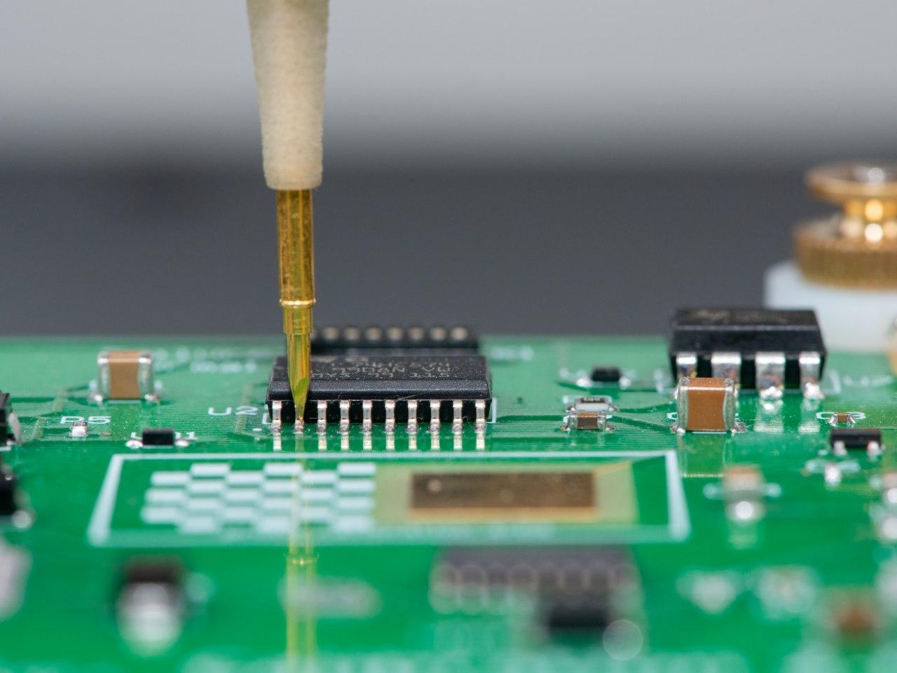
Does it sound familiar?
Does your company operate expensive and sophisticated electronic equipment, such as an electron microscope, a CNC machine, an industrial PLC, etc.? The failure of any printed circuit board (PCB) leads to a long downtime of both equipment and personnel, while the manufacturer's specialists carry out diagnostics and repairs. That's all about time and money. It seems unlikely that the manufacturer has a spare parts warehouse (SPTA) in every city. Storing the spare parts for all the boards yourself is very expensive and usually impractical. In case the device is under warranty repair costs will be paid by the manufacturer. But what if warranty has expired long ago? Complex expensive equipment can be used for 3, 5 or 10 years, and that is not the limit.
What to do in such a situation? The answer is well-known: to have the staff of highly qualified engineers who can maintain your equipment, diagnose and troubleshoot major malfunctions. It is not difficult to eliminate malfunctions because according to statistics more than 95% of PCB faults are caused by the failure of one or more electronic components in the power circuits or buffers of the power or logical interface part. The replacement of the component can be done by an electronics engineer of medium qualification for 1-4 hours. Finding of the malfunction is much more difficult though. It is easier if the documentation for the device contains circuit and wiring diagrams of the boards, but usually it is not the case since manufacturers usually provide minimal set of documents required for operation and design documentation is not included in it anyway.

Problem
For the old equipment it is common that original documentation has been long lost. How to find a malfunction without it? An electronics engineer of the highest qualification, having enough time and all the necessary equipment can certainly do the job. But it will take a lot of time and a lot of money to keep such specialists on the payroll. You need a solution that does not require documentation or super specialists.
Here's another case: you are developing small series of expensive PCBs. You already have several early prototypes that your engineers are debugging. If one or several samples were damaged or changed during the debugging process, at least insignificantly, further work with them becomes meaningless because the experiments cease to be repeatable. How can you check that those boards are still electrically identical? Writing functional tests and testing all PCBs every day is too long. Assuming that there is no problem is also not a good course of action.
Yet another case: your company is making small batch of PCBs. Since there are only few of them manual or semi-automatic soldering is used. Usually there are several defects per 1000 points of soldering. You can give it to optical control to check but it can only find defects which are visible. You can check everything manually but it takes too long. You can purchase a "flying probe" type tester with 4-8 probes for the bargain price of 500.000 and dedicate an operator to run it (by the way it can take few weeks and additional money to train operator) but this solution is not always cost efficient or even possible.
Usually you do not want to do testing, you only want to deal with your product. Therefore, a solution is required that allows checking the electrical conformity reliable, fast and cost-efficient.

Solution
EyePoint P10 is a new approach to the search of faulty electronic components on printed circuit boards. A desktop sized, inexpensive, easy-to-use, and most importantly it doesn't require original documentation for PCB. All you need to find a malfunction on the board is the reference board and EyePoint P10. Working principle is very simple. First system analyzes the reference board (the board which is known to be good) and then it compares boards under test with the reference board.
Working principle
Place the reference board into EyePoint P10, place the probe on the PCB's ground and press "Start". EyePoint P10 will do following actions automatically:
- Take a composite high-resolution photo
- Detect electronic components on PCB
- Determine the pinout
- Obtain the signature (unique volt-ampere characteristics) of each output of each electronic component with flying probe
- Save the signature of the reference board into a file
Sophisticated software
The EyePoint P10 is based on the computer vision and artificial intelligence technologies. The EyePoint P10 system purchased by you, have been trained on thousands of images of chips and chip components and is able to find them on your boards without the operator`s assistance. The list of supported components is constantly increasing. All database updates are free. At the heart of EyePoint P10 is the well developed technology of signature analysis - the comparison of the current-voltage characteristics of circuits on the board under test with the reference data. This is the safest (without feeding power to the board under study) and the quickest way to find differences between complex circuits. At the heart of the EyePoint P10 is the "flying probe" technology, which allows completely automatic testing without any operator's involvement and high precision mechanics which ensures the accuracy of the probing throughout the test.
Signature analysis
EyePoint P10 uses a method of studying current-voltage characteristics, which allows to check electronic components on the board without power supply. It is an efficient and quick way to troubleshoot PCBs. All it takes is to compare the signatures of a faulty circuit and the circuit known to be good. This method is suitable for testing circuits with passive components, such as resistors, capacitors and other semiconductor elements. It is also applicable for testing the input and output of active devices, such as integrated circuits, programmable logic arrays, and so on. The method allows to identify malfunctions quickly, including the destruction of protective diodes from static electricity or damage to output / input transistors.

During the signature analysis test an AC signal is applied to the circuit. At the same time, the current and voltage in four quadrants are measured. The software automatically compares the received signature with the sample and, based on the user defined tolerance field, decides whether the circuit under test is good or bad. The software automatically selects the appropriate frequency and voltage for the circuit under test and conducts three measurements: the first one above the optimal parameters, the second one below and the third one precisely in the optimal values to ensure reliable and repeatable results.
Reference mode
Place the reference board into the system and press "Start". EyePoint P10 moves camera over the board under test and takes a series of pictures combining them later into one high-resolution photo image. Precise positioner and intelligent algorithms for distortions elimination make it possible to achieve complete topological match of the physical board under test and it's picture. (This way specifying the point on the image with the mouse, will move the probe needle to the corresponding point on the board precisely. The scanning is fully automatic and the progress of the test is displayed on screen in real time.


Chips recognition
Using the previously obtained pictures, EyePoint P10 uses highly sophisticated software algorithms to recognize electronic components. Chip's type and arrangement of the pins are determined automatically for all the chips on the board. Obtained coordinates list (test map) will be used at the next step. If the component is missing in the library or not recognized correctly EyePoint P10 has a built-in tool for manually adding or removing components and / or test points.

Signature analysis of the reference
EyePoint P10 flying probe measures the current-voltage characteristics in automatic mode at all points of the test card (the second contact of the built-in EyePoint P10 signature analyzer is connected to ground or the common output of the reference board). Obtained signature of the reference board is saved and used later for troubleshooting.
Test mode
Loading board under test
Load board under test into the EyePoint P10 and select it from the list of the reference boards. System works completely automatically after that. It doesn't matter how accurately board under test was loaded since EyePoint P10 will compensate for the loading offsets and start testing automatically.
Testing
During test procedure, EyePoint P10 automatically compares the signatures of the reference and board under test. Defective outputs are marked in red in real time. Upon completion of the test procedure, the user will be given a complete report in HTML format, formatted for printing and subsequent analysis.

Features
- Compact footprint (desktop sized)
- Cost effective
- Does not require documentation for the boards under test
- Does not require prior operators' training
- Easy to use
- Accurate diagnostics in automatic mode
- Powerful and simple software
- Minimal human participation - less than 15 minutes per PCB
- Real time progress monitoring
- Testing without applying power to the board
- Supports more than 50 component types
- Free database updates
Specifications
- Maximum board size: 280x275 mm
- Scanning speed: 15 cm² / min
- Enclosure support: LQFP, SOIC, SMD, SOT, DIP, etc
- Creating a test card.: up to 10 cm² / min
- Testing speed: 100 points per minute
- Accuracy of probe installation: 30 microns
- Time to change the card: 30 sec
- Test voltage: up to +/- 12 V
- Sensitivity to R: 2 Ohm - 450 kOhm
- Sensitivity to C: 300 pF - 100 uF
- Sensitivity to L: from 270 μH
- Dimensions and weight: 604х543х473 mm, 50 kg
- Managing PC: Intel i5 2.8 GHz, 16 GB RAM, 256 GB SSD
- Power supply: ~ 120V, 300W